1.5 Cables, Conditioning and Grounding
about 18 minutes · 2 figures · quiz of 5 · Slides
After this section you can: power and cable an IEPE or charge sensor for the run length and frequency, and keep ground loops and cable noise out.
Between the sensor and the converter the signal travels a cable, passes through a conditioner and crosses at least one ground. Each of the three can change it, and none of them shows on the control plot as anything but a slightly wrong number. This section takes the IEPE cable first, because the loop chapters (Chapter 3, Chapter 4) send the reader here for it, then the conditioner, then the noise a cable can make and the hum a ground can put in.
An IEPE sensor's amplifier drives its own cable. The cable has capacitance, and every swing of the signal has to charge and discharge it, using the constant current the conditioner supplies. When the signal swings faster than that current can charge the cable, the waveform cannot follow: the peaks are rounded or slewed, and the reading comes out low at high frequency and high level, which is where a shock or a resonance lives. One sensor manufacturer's technical note on driving long cables (PCB Piezotronics TN-7) gives the highest frequency a given setup can carry without that distortion as:
where:
- : highest frequency the setup can carry without distortion, Hz
- : constant current from the conditioner, mA; the note subtracts 1 mA as the share the sensor's own amplifier uses
- : the cable's total capacitance, pF
- : peak output voltage, V
- The equation works only in these units; the converts milliamps over picofarads to hertz.
The same note advises setting the current so that is 1.5 to 2 times the highest frequency of interest, and treats runs beyond about 100 ft (30 m) as a concern for high-frequency, shock and transient work.
Worked through for a cable whose datasheet gives, say, 30 pF per foot (the arithmetic is the author's): 100 ft is 3,000 pF. At the full 5 V of output and 4 mA, is about 31,800 Hz, far above any shaker band. At 2 mA it is about 10,600 Hz. Make the run 300 ft, 9,000 pF, out to a control room on the far side of a large facility, and at 2 mA it falls to about 3,500 Hz. For a random test to 2,000 Hz that meets the note's 1.5 times and falls short of its 2 times; at 4 mA it is about 10,600 Hz again. Two things follow. The voltage in the relation is the peak, so the limit is worst exactly when the signal is largest, at the resonance or the pulse, and a channel that is clean at the low level, the reduced-level run made before the full-level one, can distort at full level. And the current is a conditioner setting on some racks and fixed on others, so the run length and the current are both checked, not assumed.
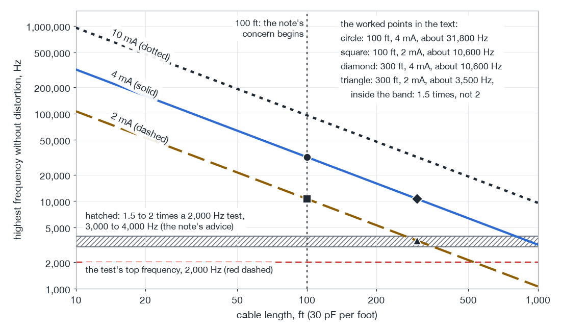
From the long-cable relation in the text: 30 pF per foot, 5 V peak output. Dotted 10 mA, solid 4 mA, dashed 2 mA. The worked points are the text's arithmetic.
The low end of the chain is the other limit. A piezoelectric chain cannot hold a steady level, so it behaves as a high-pass filter whose corner is set by its time constant:
where:
- : corner frequency of the high-pass, Hz
- : time constant, s
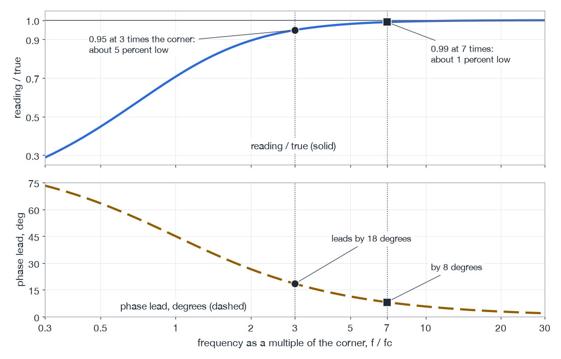
The sensor has one, set when it was made (1.2). The conditioner's coupling has one, and the controller's input, set to AC coupling, has another. The shortest of them governs, so a sensor with a long time constant on an input with a short one has the input's corner. Above the corner the reading approaches the truth slowly. A single high-pass reads about 5 percent low at three times its corner and about 1 percent low at seven times, and it leads the true phase by about 18 degrees and 8 degrees there (the author's arithmetic, from the filter's own shape: at times the corner the reading is of the truth, 0.949 at three and 0.990 at seven). Take a long-stroke sine that starts at 5 Hz, on a chain whose shortest time constant is 0.1 second: the corner is 1.6 Hz, 5 Hz is about three times it, and the channel reads about 5 percent low. On a control channel the controller sees 5 percent too little and raises its drive (the signal it sends the amplifier, which the amplifier turns into the shaker's motion) by 5 percent, so the table is 5 percent over the profile at the bottom of the sweep, which is where the stroke is tightest. With a one-second time constant the corner is 0.16 Hz, and at 5 Hz the error is gone. A transport random that reaches down to 2 or 3 Hz is the same case lower in frequency, and its channels are checked the same way (11.3). The same filter puts an undershoot after a long shock pulse and a velocity that does not come back to zero, which is part of why shock below 2 Hz goes to a piezoresistive sensor (1.2). A high-pass also has to settle. The manufacturer's introduction to IEPE sensors cited in 1.2 gives full discharge after about five time constants, so after power-up or after an overload (1.8) the channel's baseline wanders for that long, and a channel used before it settles drifts.
a. A single high-pass
Reading over the truth (solid) and phase lead (dashed) against frequency as a multiple of the corner; circle at 3 times, square at 7 times.
b. Two chains at the bottom of a 5 Hz sweep
A true 1 g peak sine at 5 Hz and what two chains report: shortest time constant 0.1 s (corner 1.6 Hz) and 1 s (corner 0.16 Hz).
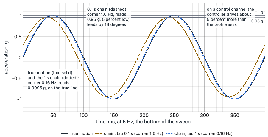
Synthetic, normalized to 1 g peak; steady state. The chain's shortest time constant governs.
Choosing AC or DC coupling at the input is 2.1's subject. What belongs here is that the low-frequency limit is a property of the whole chain, worked out from its shortest time constant and written in the channel table beside the high-frequency limit from the mount (1.4).
The conditioner sets a gain, and that is where the two-number problem lives. Where an external conditioner sits between the sensor and the controller, the scaling is split in two: the conditioner's gain against the sensor, and the sensitivity the controller is told against the conditioner's output. Either one wrong mis-scales the channel, and the controller's own check cannot tell which (4.3). The fix is to decide where the sensitivity lives and to put it there once. One way sets the conditioner to unity gain and enters the sensor's certificate value in the controller. Another sets the conditioner to scale its output to a round figure per g and enters that figure in the controller. Either works. What does not work is half of each, or a conditioner gain changed for one test and never changed back. Whichever way the lab chooses, it is written in the channel table, and the calibrator check of 1.7 reads it back through the whole chain to the screen.
A cable can also make its own signal. In a charge system the cable between the sensor and the charge amplifier carries a few picocoulombs at very high impedance, and an ordinary coaxial cable that flexes makes charge of its own as its shield and insulation rub, the triboelectric effect. It shows up as spikes and low-frequency wander that follow the cable's motion. The answer is the low-noise cable made for charge sensors, kept short, tied down so it cannot whip, with clean, dry connectors (1.2). IEPE cables carry a low-impedance signal and are far less sensitive to it, but every cable on a shaker suffers the mechanical faults. A loose cable whips, and a whipping cable fatigues its connector, pulls on the sensor and puts its own motion into a light one. The Bruel and Kjaer handbook gives cable whip and connector fatigue as the reasons to tie cables down. Every cable is strain-relieved at the sensor with a loop and a tie, then clamped at intervals along the fixture, dressed to the fixture the way the article's instrumentation leads are, and never run to the shaker's hood. A connector inside a chamber is sealed against condensation, because water across a connector is a leak path, and on a charge sensor a leak path takes the low frequencies with it. Instrument cables are kept apart from the amplifier's output cables and away from the shaker body where they can be, and cross other cables at right angles rather than running alongside them.
The worst noise in most labs is not the cable's own. It is a ground loop. A sensor whose case touches the fixture is connected, through the fixture and the armature, to the shaker body, and the body is grounded at the amplifier. The conditioner or the controller is grounded through its own power cord, at its own outlet. The cable's shield joins the two grounds, and if they sit at slightly different voltages, as two grounds in a building with a large amplifier in it usually do, a current flows between them along the shield and becomes a voltage in the measurement. The Bruel and Kjaer handbook works an example in which the ground-loop noise is many thousands of times the cable's own triboelectric noise. Its signature is the line frequency, 60 Hz in North America and 50 Hz in most of the rest of the world, and its harmonics: a comb of narrow, steady peaks that is there with the drive at zero and often changes when the amplifier is switched on, because the shaker body's potential changes with it.
The cure is one deliberate ground for the measurement system: the loop broken at one place, chosen, and left that way. At the sensor that means an isolated stud, an insulating disc or a sensor with an insulated base (1.4), which costs a little mounted resonance. A sensor glued to polyimide tape is isolated the same way. A sensor glued or cemented straight to the article is isolated only while the adhesive keeps the metal apart: pressed down too hard, its base meets the surface through a squeezed-out glue line and the loop is closed again, and some labs mix a few small glass beads into the epoxy or cement so that the layer cannot be pressed thinner than the beads. At the rack it means inputs that do not tie the shield to the rack's ground, where the system has them. The protective earth on the amplifier, the controller and every other piece of mains equipment is never lifted to cure hum. That ground is there to keep a fault from putting line voltage on the shaker body, and a lab that cuts it to clean up a spectrum has traded noise for a shock hazard.
The hum that was not the article's. A functional test ran the article powered on the shaker, its own electronics live and their outputs watched while it vibrated. Before the first low level, the response channels on its chassis showed a comb of narrow peaks at the line frequency and its harmonics, steady, with the drive at zero. The article's engineers took it for their power supply leaking into the chassis, and the day went to the supply. The comb did not move when the article was switched off. It came and went with the shaker's amplifier. The sensors' cases sat on the article's chassis, the chassis was bolted through the fixture to the shaker body, the body was grounded at the amplifier, and the conditioners were plugged into an outlet across the room, grounded somewhere else, with the cable shields joining the two. Insulating discs went under the sensors, and at the next low level the comb was gone. The article had been on the shaker for a day with nothing wrong with it.
Decide. Give the measurement system one deliberate ground, break any loop at the sensor or at an isolated input, and never lift a protective earth. Check every IEPE run's length and current against the highest frequency at full-level peak output, and work out every chain's low-frequency limit from its shortest time constant. Tie down and strain-relieve every cable. Decide where each channel's sensitivity lives, enter it once for the whole chain, and read it back through the chain to the screen.
Common Questions
Does the cable limit matter at the low level as well?
Less than at full level. The highest frequency a run can carry falls as the peak output voltage rises, so the limit is worst at the resonance or the pulse, at full level (1.5). A channel that is clean at the low level can still distort at full level, which is why the run is checked against full-level peak output.
The rack's constant current is fixed and the run is long. What can be done?
Work the relation with the current the rack gives (1.5). If the result is short of 1.5 to 2 times the top of the band, the capacitance has to come down, since the highest frequency rises as the cable's total capacitance falls: a shorter run, or a cable with less capacitance per foot. The run length and the current are both checked, never assumed.
Can the ground pin on a conditioner's power cord be lifted to kill hum?
No. The protective earth on the amplifier, the controller and every other piece of mains equipment is never lifted, because it keeps a fault from putting line voltage on the shaker body (1.5). The loop is broken at the sensor, with an isolated stud, an insulating disc, a sensor with an insulated base or polyimide tape (1.4), or at the rack with inputs that do not tie the shield to ground.
Should the sensitivity live in the conditioner or in the controller?
Either, once. One way sets the conditioner to unity gain and enters the certificate value in the controller; another scales the conditioner to a round figure per g and enters that figure (1.5). What fails is half of each, or a gain changed for one test and never changed back. The choice is written in the channel table and read back by the calibrator check (1.7).
Quiz: Try It
Open book. 5 questions drawn from this section's pool. 4 correct passes the quiz. Nothing is recorded here; in the course your passing attempt opens the next section.