1.4 Mounting
about 19 minutes · 2 figures · quiz of 5 · Slides
After this section you can: prepare a surface, choose a mount, torque it, and state its usable frequency limit and why.
The mount is the first link in the chain and the one most often made in a hurry. It decides the mounted resonance, and the mounted resonance decides the highest frequency the channel can be trusted to (1.3). Everything in this section is about keeping that resonance high and keeping it from changing during the run. Volume 1 takes the fixture's side in its fixtures chapter, the tapped mounts designed into it at the mounting points and the control point; this section takes the sensor's side. MIL-STD-810H points to IEST-RD-DTE012.2, the handbook for dynamic data acquisition and analysis, for mounting practice, and ISO 5348 is the standard on mounting accelerometers, including how a mounted resonance is determined.
Start with the surface. The sensor's base and the surface it sits on have to touch all over, because the contact between them is the stiffest spring in the mount and anything that holds the base off it makes the spring softer. One sensor manufacturer's installation guide (Endevco TP319) asks for the surface under the base to be flat within 0.0003 in total indicator reading (the full swing of a dial indicator run across it) and finished to a roughness of 32 microinch. Those are that guide's figures for its sensors; the sensor's own installation note governs. A painted, anodized or cast surface, a burr thrown up around a tapped hole, the first raised thread at the hole's mouth: each holds the base off the surface somewhere and lowers the resonance. Where the surface is rough, it is spot-faced; where a hole has a burr, it is deburred; and everything is cleaned before the sensor goes down.
The tapped hole is square to the surface. A hole drilled at an angle cocks the sensor, so it sits on an edge of its base with a gap under the rest, and its axis points a little across the test axis as well. The hole is deep enough, and the stud short enough, that the stud does not bottom in the hole or in the sensor's base. A stud that bottoms takes the torque on its end instead of clamping the base, and the sensor sits loose on its base with full torque on the wrench. The Bruel and Kjaer handbook warns of large errors from it, and it is the mounting fault least likely to be suspected, because the wrench clicked.
A thin layer of silicone grease between the base and the surface fills the small gaps that flatness and finish leave. The Bruel and Kjaer handbook gives it as improving the high-frequency response, and the Endevco guide says the lubricant matters above about 2 kHz. A film that fills the gaps is the goal; a thick layer is a spring of its own.
Then the torque, with a torque wrench, every time. Under-torque lowers the mounted resonance, and a stud that is barely snug can loosen under vibration and turn a good mount into the opening story's. Over-torque strips the threads in the sensor or the surface, or breaks the stud. The Bruel and Kjaer handbook gives 1.8 N·m for a 10-32 UNF stud and 0.6 N·m for an M3 stud for its sensors, which is about 15.9 and 5.3 in-lb (the conversion is the author's). The sensor's datasheet gives the torque for that sensor, and that is the one used. The torque is written down, as it is for the fixture's own joints.
a. The stud mount done right
Grey cross-hatching is the fixture; blue dots are the grease film; a dashed red outline marks the fault. The geometry is exaggerated to show it.
With the surface ready, the mount itself is a choice, and the choices rank by how high they keep the mounted resonance and how well they hold.
The stud is the reference. It gives the highest mounted resonance the sensor can have, it holds through any level and any temperature the sensor can stand, and it is the mount the sensor was calibrated on. A fixture with tapped holes at the control point and the mounting points has made the choice already.
Adhesive comes next. A thin, hard glue line, cyanoacrylate (instant glue) or a stiff epoxy, gives a mounted resonance close to the stud's when the surface is flat and the line is thin, and it puts a sensor on a surface that cannot be drilled, which is most articles. Dental cement, a quick-setting cement labs use for the purpose, fills an uneven or curved surface. Every adhesive has a cure time, and a channel on an adhesive that has not cured is a channel on a soft spring. Every adhesive has a temperature range too, and a cemented sensor that lets go partway through a cold soak is what happens outside it. Many labs now lay a strip of polyimide (Kapton) tape on the article first and glue the sensor to the tape with instant glue: the tape protects the article's surface, makes removal clean and insulates the sensor's case from the article (1.5). It is also one more layer that can let go, and sensors on tape and instant glue work loose more readily than sensors on a hard glue line on bare metal, above all on combined thermal and vibration tests, where more often than not the mount has to change to an epoxy or dental cement. The adhesive is also how sensors get broken: a glued sensor is removed by the solvent made for that adhesive and patience, with at most a removal tool made for the sensor, never by striking it or prying it sideways. The Endevco guide says most damage to miniature sensors comes from improper removal.
As a procedure, an adhesive mount takes five steps. Clean the spot to bare metal where the owner allows it, or to the finish the owner has agreed, and degrease the spot and the sensor's base with the solvent the adhesive's instructions name, isopropyl alcohol being a common one, and let both dry. Use the least adhesive that wets the whole base: pressed down and turned a little to seat it, the base should squeeze out a small bead all round and leave a thin, even line under it, not a layer. Hold it for the time the instructions give, and do not mistake that handling time, a minute or so for an instant glue, for the cure: the adhesive manufacturer's full-cure time, often hours and for some epoxies a day, passes before the channel carries a full-level run. Check the adhesive's temperature range against the test's at both ends. And write the adhesive, the time the mount was made and its cure time in the channel table, so whoever runs the next step knows whether the channel is ready.
A cementing stud combines the two. It is a small flat pad with a tapped hole in it, glued to the surface, and the sensor screws onto it at its stud torque. The glue line is made once, with the care it needs, and the sensor can come off and go back on, or be turned to a new orientation, without breaking it. On an article that will be tested in three axes with sensors moved between them, cementing studs placed before the first axis save a remount at every change.
A magnetic base clamps a sensor to a steel surface in seconds, and on a shaker that is less useful than it sounds. Most fixtures are aluminum or magnesium, where it will not hold at all. The magnet is extra mass and a softer joint than a stud, so it lowers the mounted resonance, by an amount that depends on the magnet, the sensor and the surface. And a magnet let snap onto steel puts a sharp shock into the sensor; it is eased on, at an angle and rocked down, never dropped. The magnet is for a quick survey on steel and for the facility checks of Volume 1, on the shaker's body, a pump or a floor, not for a test channel.
Beeswax holds a light sensor to a smooth surface for a quick look. The Bruel and Kjaer handbook limits it to about 40 C (104 F) and to about 10 g, so it is a survey mount at low level and room temperature and nothing else.
A hand-held probe, a sensor on a stinger pressed against the surface, is for spot checks, and the Bruel and Kjaer handbook limits it to below about 1,000 Hz. It is how a technician finds which panel on a machine is buzzing. It is not a measurement anyone signs.
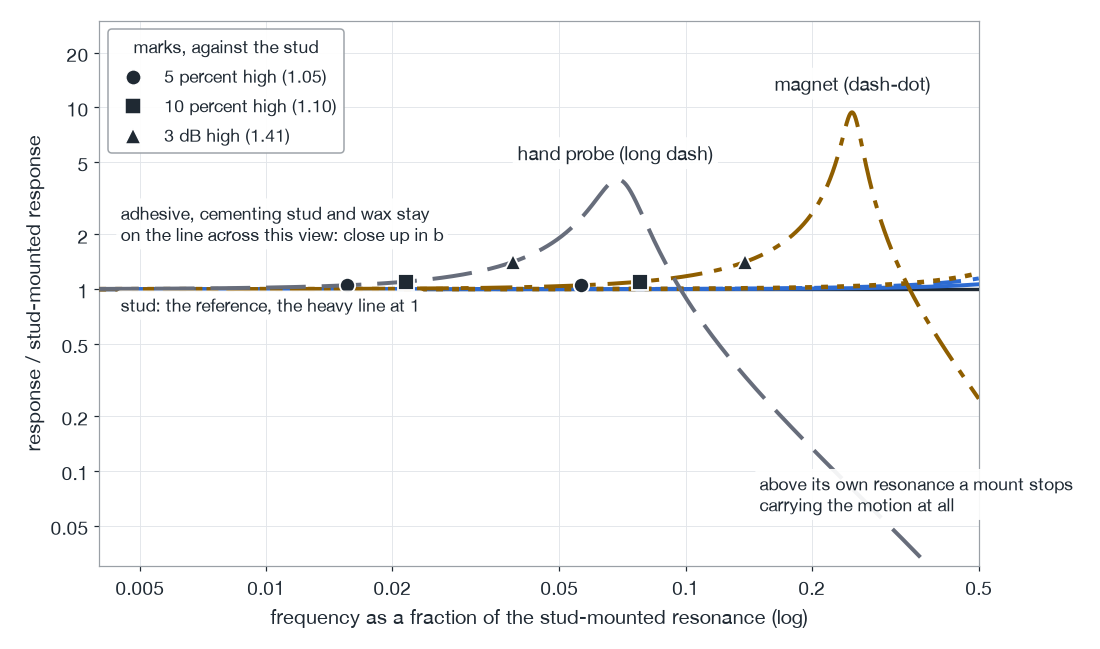
a. Six mounts on one sensor
Response on each mount over the stud-mounted response, against frequency as a fraction of the stud-mounted resonance. Marks where each curve leaves the flat line by 5 percent (circle), 10 percent (square) and 3 dB (triangle).
b. The three highest mounts, close up
Adhesive, cementing stud and wax, on a linear scale near the top of the stud's usable range; hollow marks are the stud's own 5 percent, 10 percent and 3 dB points.
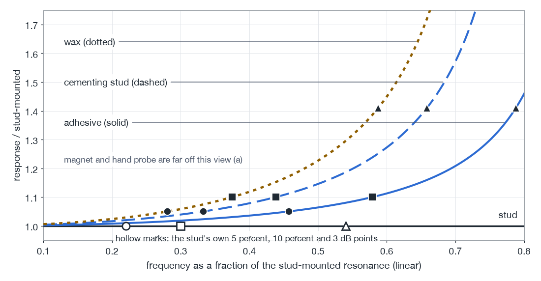
A model, not bench data: mounted resonances 1.00, 0.92, 0.85, 0.80, 0.25 and 0.07 of the stud's, Q 25 down to 4, all assumed. The ranking is the lesson; the frequencies belong to this model.
That caption carries the rule for the numbers. Every published figure for a mounting method was measured with one sensor on one rig, and a different sensor, a different surface or a different torque gives a different number. The ranking travels from sensor to sensor; the frequencies do not. What does travel is the fraction of mounted resonance. A test engineer who knows the mounted resonance of the mount in use, from the sensor's own notes or by measurement, applies the arithmetic of 1.3 and has the channel's usable limit.
Two field measurements give it. The quicker is a tap. With the sensor on its mount, a light tap from a small hard tool beside the mount rings the sensor on its mount, and the channel's spectrum shows the mounted resonance as a peak standing above everything near it. The record has to be made where the resonance can be seen: on a spare input or a recorder sampling several times the expected resonance, with its anti-alias filter set well above it, because a controller input set for a 2,000 Hz test filters away the very peak being looked for (2.2). The other is a comparison. A reference sensor is stud-mounted beside the sensor under question on the same stiff surface, or the two are mounted back to back on a calibration exciter, and the pair is swept slowly toward the top of the band at a low level. Where the mounted sensor starts to read above the reference it is climbing the curve of Figure 1.3, and the frequency at which it reads 5 percent high is that channel's usable limit, read directly instead of computed. Either result goes in the channel table with the mount it was measured on.
Two kinds of hardware sit between a sensor and the surface on many setups, and both cost something. A mounting block or adapter, used to put a single-axis sensor on a face at right angles to the surface or to clock a sensor to a feature, adds a joint and a mass. The Endevco guide says magnesium and aluminum blocks compromise the response above about 10 kHz and asks that the sensor be calibrated with its block. For most shaker tests, with bands that stop well below that, a stiff block is fine, as long as it is in the channel table and the usable limit accounts for it.
The second is isolation. A sensor whose case touches the fixture puts the fixture's electrical ground, which is the shaker body's, on its cable's shield, and that can close a ground loop (1.5). An isolated stud, an insulating disc of mica or another insulator under the base, or a sensor with an insulated base breaks the path. The cost is another layer in the stack, which lowers the mounted resonance; the Bruel and Kjaer handbook notes a mica washer doing so, more so above 80 C. A sensor with its isolation built in costs least in resonance, and where ground loops are a known problem on a setup, it is the sensor to buy.
Where the sensor goes decides much of this. A control sensor on the fixture sits in a tapped hole made for it, at a stud's resonance (1.6). Response sensors on the article usually cannot: the owner will not let the article be drilled, the surface is painted, curved or thin, and the mass that a fixture never notices is a real fraction of a cover panel (1.3). That is the case for adhesives and cementing studs, for the owner's agreement on surface preparation before the article arrives, and for the mass check. The location, the mount, its frequency limit and its orientation are recorded for every channel, and the orientation is photographed against a feature of the article.
Decide. At full level, only a stud or a fully cured adhesive mount carries a channel; cementing studs count as studs once their glue line has cured. Wax and magnets are survey mounts, and the hand probe is a spot check. Every mount is torqued with a wrench to the sensor's datasheet value, and the torque is written down. Every channel's usable frequency limit, from its mounted resonance and the fraction the requirement allows, is written beside it in the channel table (2.4).
Common Questions
Is instant glue on polyimide tape good enough for a full-level channel?
Fully cured, it is an adhesive mount, and an adhesive mount may carry a channel at full level (1.4). The tape is one more layer that can let go, though, and sensors on tape work loose more readily than sensors on a hard glue line on bare metal, above all on combined thermal and vibration tests, where the mount usually has to change to epoxy or dental cement. What the tape buys is clean removal and an insulated case (1.5).
The datasheet is not at hand. Can the stud be snugged by feel?
No. The chapter asks for a torque wrench every time, set to the sensor's datasheet value, with the torque written down (1.4). Under-torque lowers the mounted resonance and lets a stud loosen in the run, as in the opening story; over-torque strips the threads or breaks the stud.
Why does a magnetic base rank so low when it is so quick?
Most fixtures are aluminum or magnesium, where it does not hold at all (1.4). On steel it adds mass and a softer joint that lower the mounted resonance, and a magnet let snap onto the surface puts a sharp shock into the sensor. It is a survey mount, for a quick look on steel and the facility checks, never a test channel.
What goes in the channel table as the mount's usable frequency limit?
The mounted resonance of this sensor on this mount, times the fraction the requirement allows, about 0.22 for 5 percent (1.3). Published figures for a mounting method travel only as a ranking, not as frequencies, and a mounting block or an insulating disc in the stack lowers the resonance and is counted in it (1.4). The limit is written beside the channel (2.4).
Quiz: Try It
Open book. 5 questions drawn from this section's pool. 4 correct passes the quiz. Nothing is recorded here; in the course your passing attempt opens the next section.