The base touching the surface all over: the contact is the stiffest spring in the mount
One guide: flat within 0.0003 in TIR, finished to 32 microinch; the sensor's own note governs
Spot-faced, deburred and cleaned; the tapped hole square to the surface
The stud never bottoms, in the hole or in the sensor's base
Grease and Torque
A thin film of silicone grease fills the gaps; a thick layer is a spring of its own
A torque wrench every time, to the sensor's datasheet value, and the torque written down
Under-torque lowers the resonance and loosens in the run; over-torque strips threads or breaks the stud
A Stud Mount, Right and Wrong
Flat surface, square hole deeper than the stud, thin grease, base seated, stud clear
Three faults: the stud bottomed, the hole at an angle, the base held off by a burr
a. The stud mount done right
Grey cross-hatching is the fixture; blue dots are the grease film; a dashed red outline marks the fault. The geometry is exaggerated to show it.
Figure 1.4. A stud mount in section, the way it should be: a flat, spot-faced surface, a tapped hole square to it and deeper than the stud, a thin film of grease, the sensor's base seated all over, the stud clear of the bottom of the hole and of the sensor, and the torque written beside it. Three faults are drawn beside it, each with what it does to the mounted resonance: the stud bottomed, the hole drilled at an angle, the base held off by a burr.
Stud and Adhesive
The stud is the reference: highest resonance, holds at any level, the mount it was calibrated on
A thin, hard glue line of cyanoacrylate or stiff epoxy comes close; dental cement fills a curved surface
Every adhesive has a cure time and a temperature range
Removed with its solvent and patience, never struck or pried sideways
Cementing Studs, Magnets, Wax and the Hand Probe
Cementing stud: a pad glued once, the sensor screwed on at stud torque, removable and re-clockable
Magnet: steel only, extra mass and a softer joint; eased on, never let snap
Wax: about 40 C and about 10 g, a survey mount
Hand probe: spot checks below about 1,000 Hz
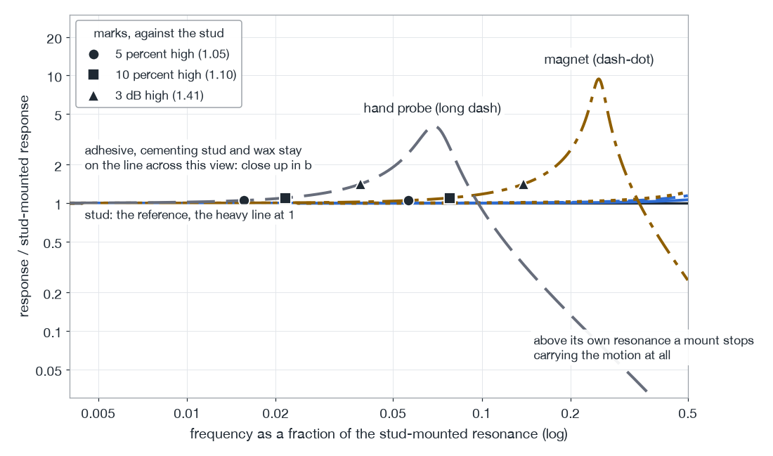
Six Mounts, One Sensor
The ranking travels from sensor to sensor; the frequencies do not
What travels is the fraction of mounted resonance
a. Six mounts on one sensor
Response on each mount over the stud-mounted response, against frequency as a fraction of the stud-mounted resonance. Marks where each curve leaves the flat line by 5 percent (circle), 10 percent (square) and 3 dB (triangle).
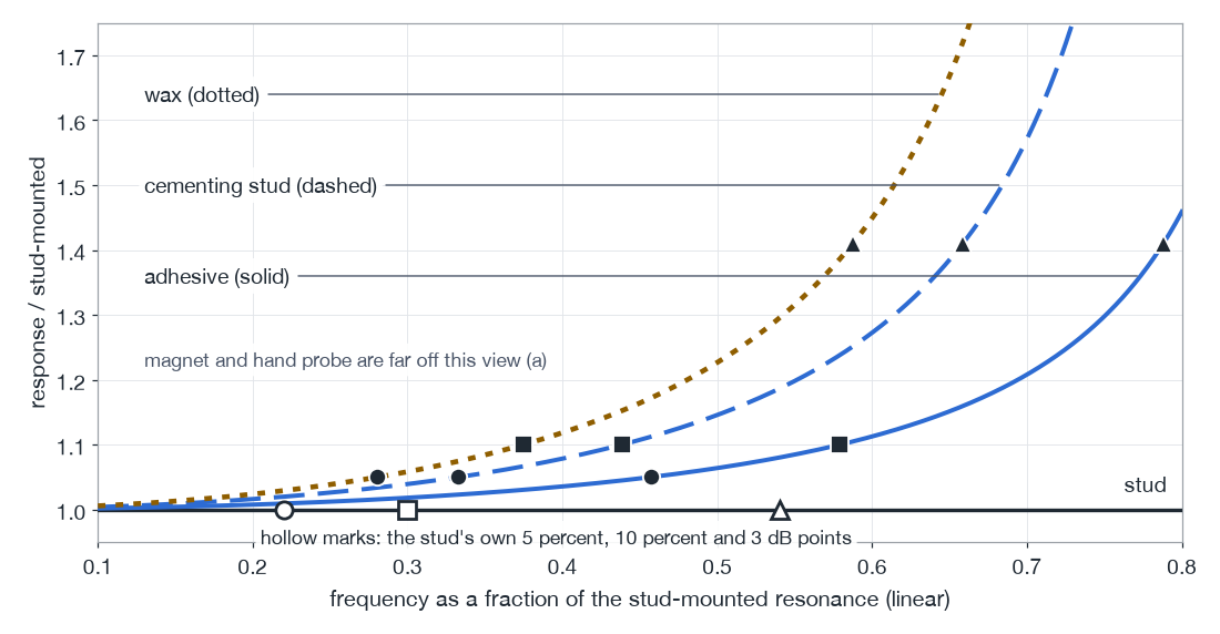
b. The three highest mounts, close up
Adhesive, cementing stud and wax, on a linear scale near the top of the stud's usable range; hollow marks are the stud's own 5 percent, 10 percent and 3 dB points.
A model, not bench data: mounted resonances 1.00, 0.92, 0.85, 0.80, 0.25 and 0.07 of the stud's, Q 25 down to 4, all assumed. The ranking is the lesson; the frequencies belong to this model.
Figure 1.5. One sensor's response on six mounts, as a ratio to its stud-mounted response, across frequency as a fraction of its stud-mounted resonance: stud, adhesive, cementing stud, magnet, wax and hand probe. The 5 percent, 10 percent and 3 dB marks of Figure 1.3 are drawn on each mount's curve. The ranking holds for any sensor; the frequencies where each curve leaves the flat line belong to this sensor on this rig, and are read for another sensor from its own mounted resonance.
Blocks, Isolation and Where the Sensor Goes
A mounting block adds a joint and a mass: calibrate with it, count it in the limit
An isolated stud, insulating disc or insulated base breaks a ground loop, at a cost in resonance
The control sensor in a tapped hole on the fixture; response sensors on the article, usually glued
Decide
At full level, only a stud or a fully cured adhesive; cured cementing studs count as studs
Wax and magnets are survey mounts; the hand probe is a spot check
Every mount torqued with a wrench to the datasheet value, and the torque written down
Every channel's usable frequency limit written beside it in the channel table
This page is part of the KCSC Training course and is licensed to one named reader for viewing. It does not print. Lab kit pages print from the Lab Kit menu.